Auro Lamp
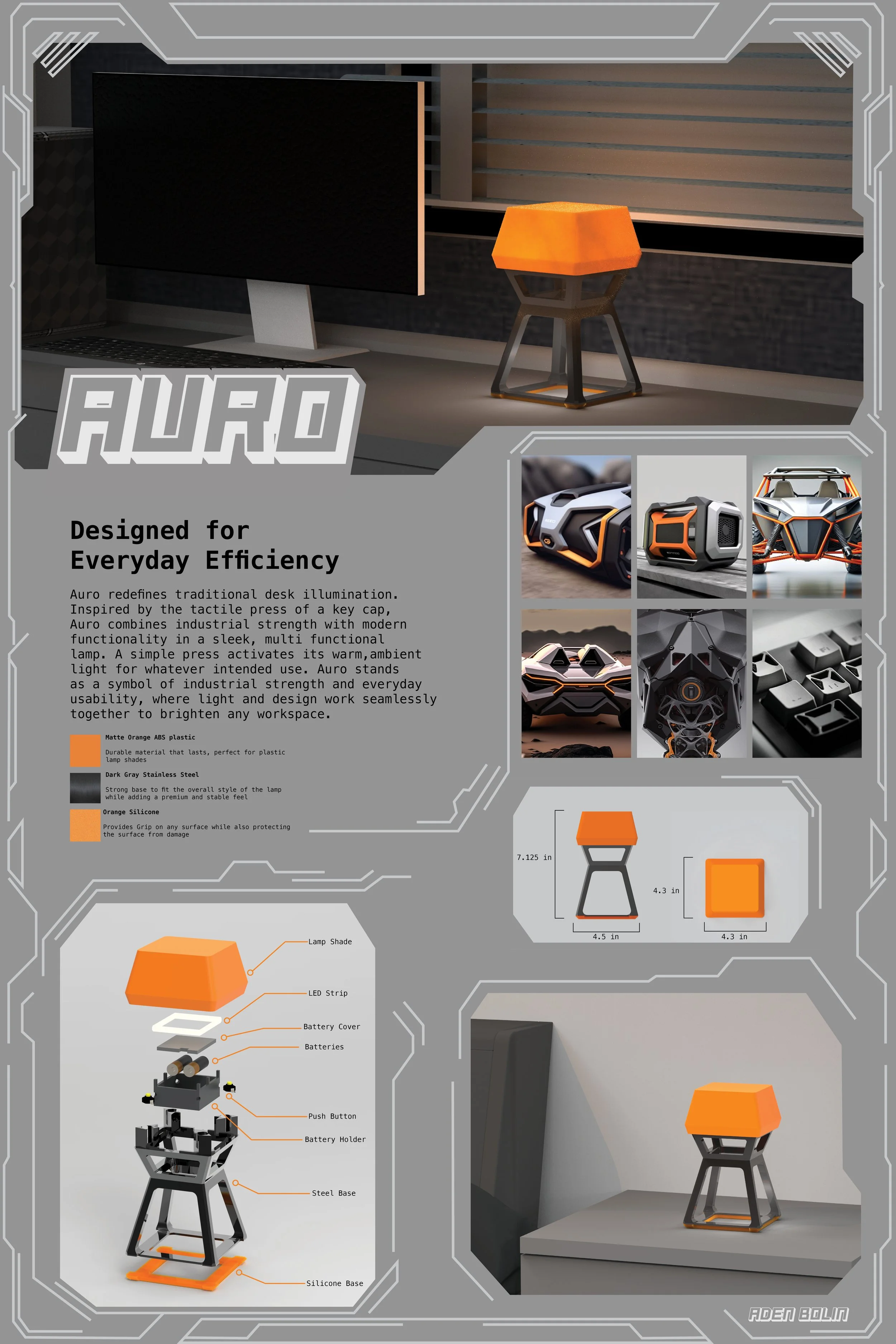
This five-week project focused on designing the Auro Lamp, beginning with mood boards and a defined setting to guide its aesthetic and functional direction. Through iterative form exploration, 3D modeling, and 3D printing, the design evolved to accommodate internal electronic components while maintaining a clean, cohesive exterior. The final prototype demonstrates a balance between technical constraints and refined visual design.
Design Goals
Defining the Objectives of the Project
Hide internal parts without disrupting the lamp’s clean form.
Arrange components to keep the design simple and uncluttered.
Match the lamp’s style to the chosen mood board.
Use consistent shapes and details to create a unified look.
Place controls where users naturally reach.
Make interaction simple, clear, and easy to understand.
Mood Board
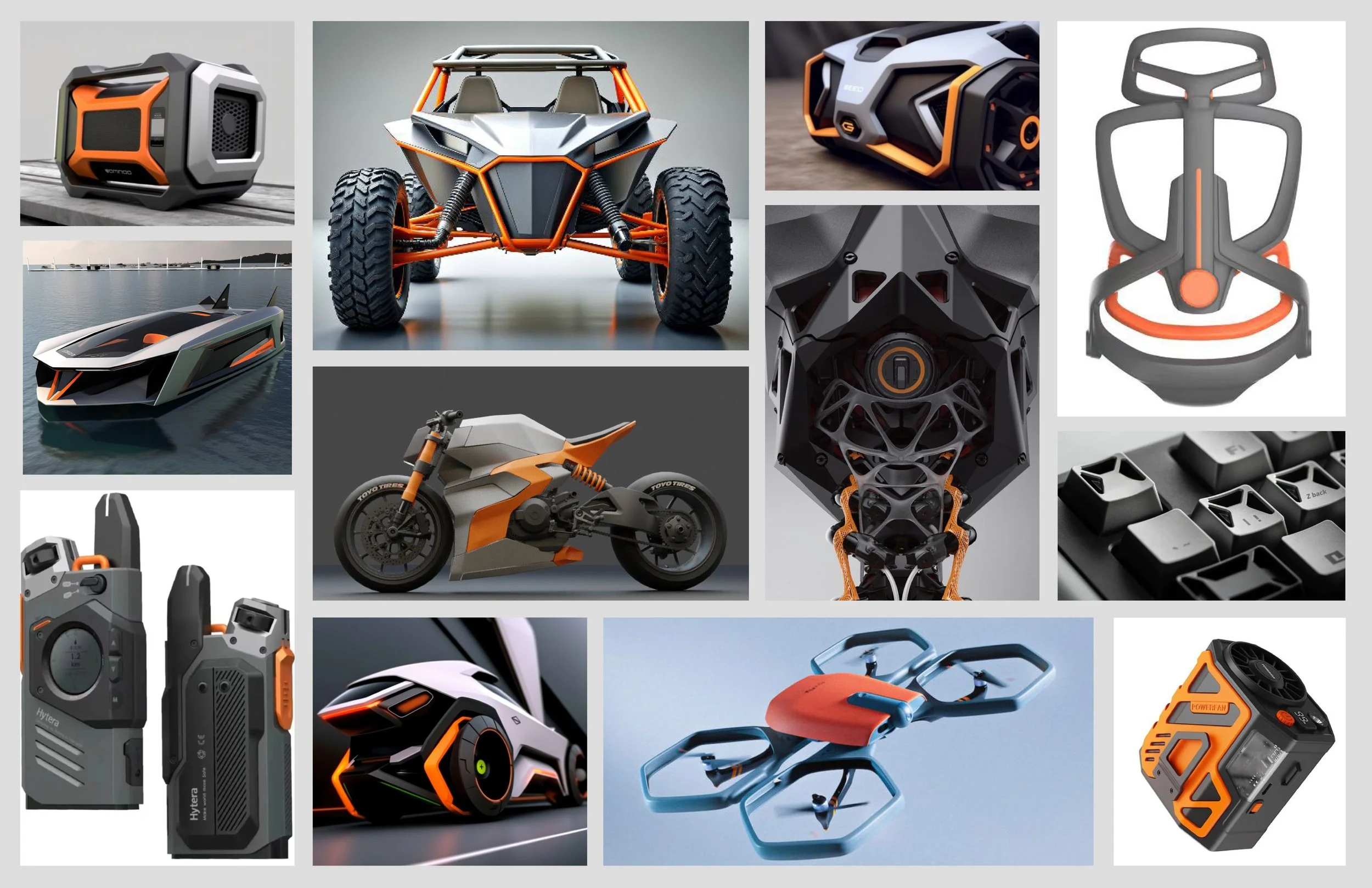
Highlighted geometric shapes and strong industrial frameworks
Pulled inspiration from vehicle chassis and exposed structures
Explored futuristic and robotic visual cues for form direction
Focused on rigid lines, clean surfaces, and structural clarity
Established an industrial, tech-forward aesthetic foundation for ideation
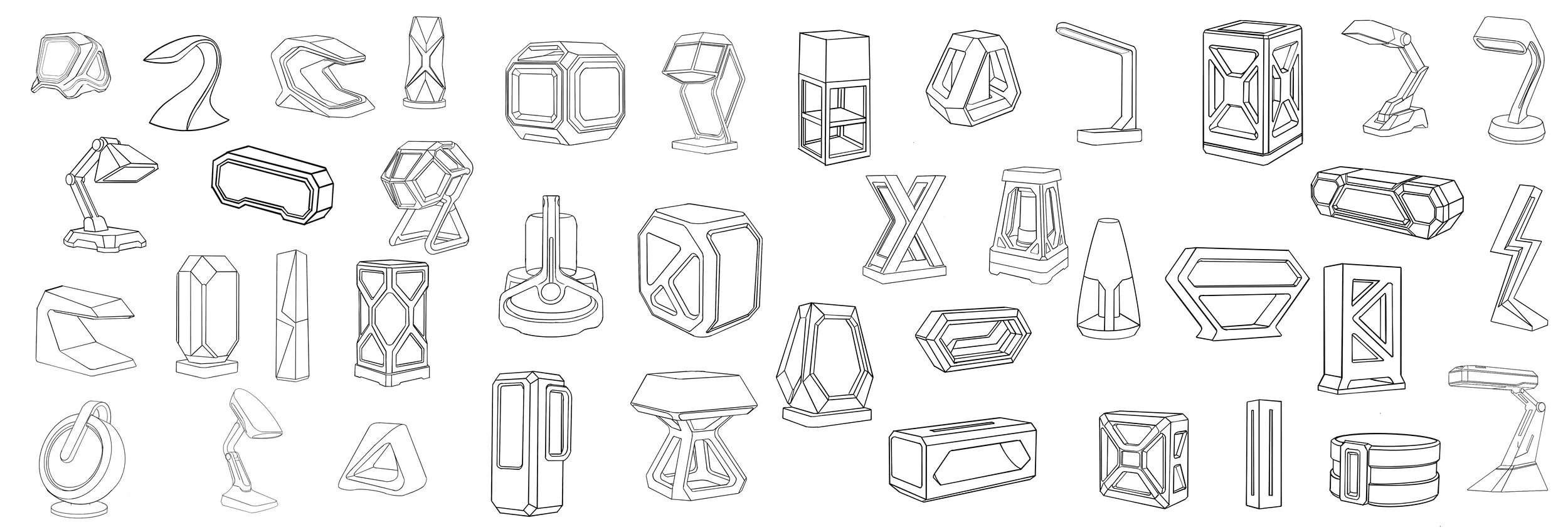
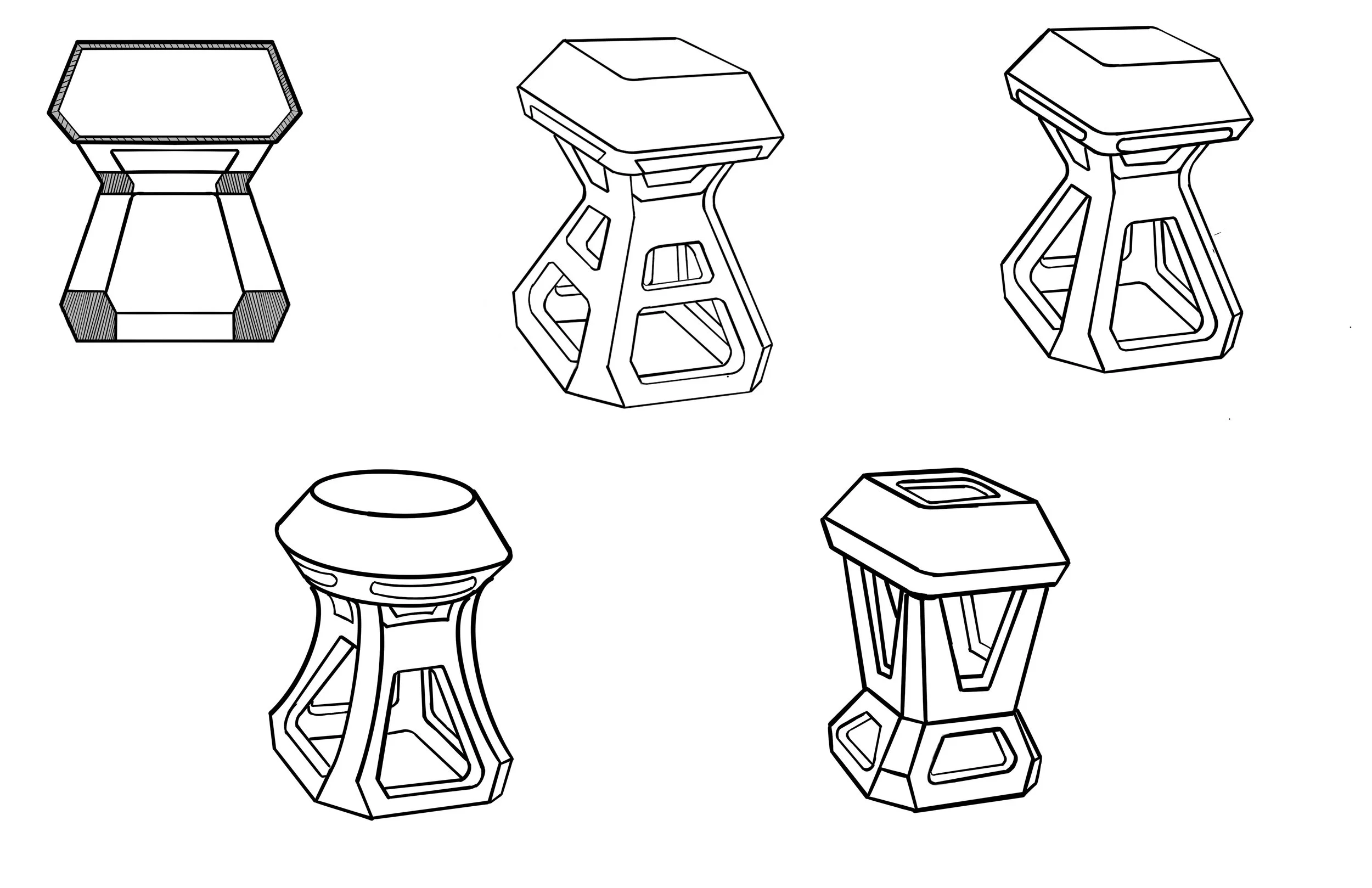
Ideation Sketches
Early Concepts Driven by Mood Board
Explored geometric forms inspired by industrial and robotic frameworks
Sketched futuristic silhouettes built from clean structural shapes
Combined rigid frames with tech-forward details for early concepts
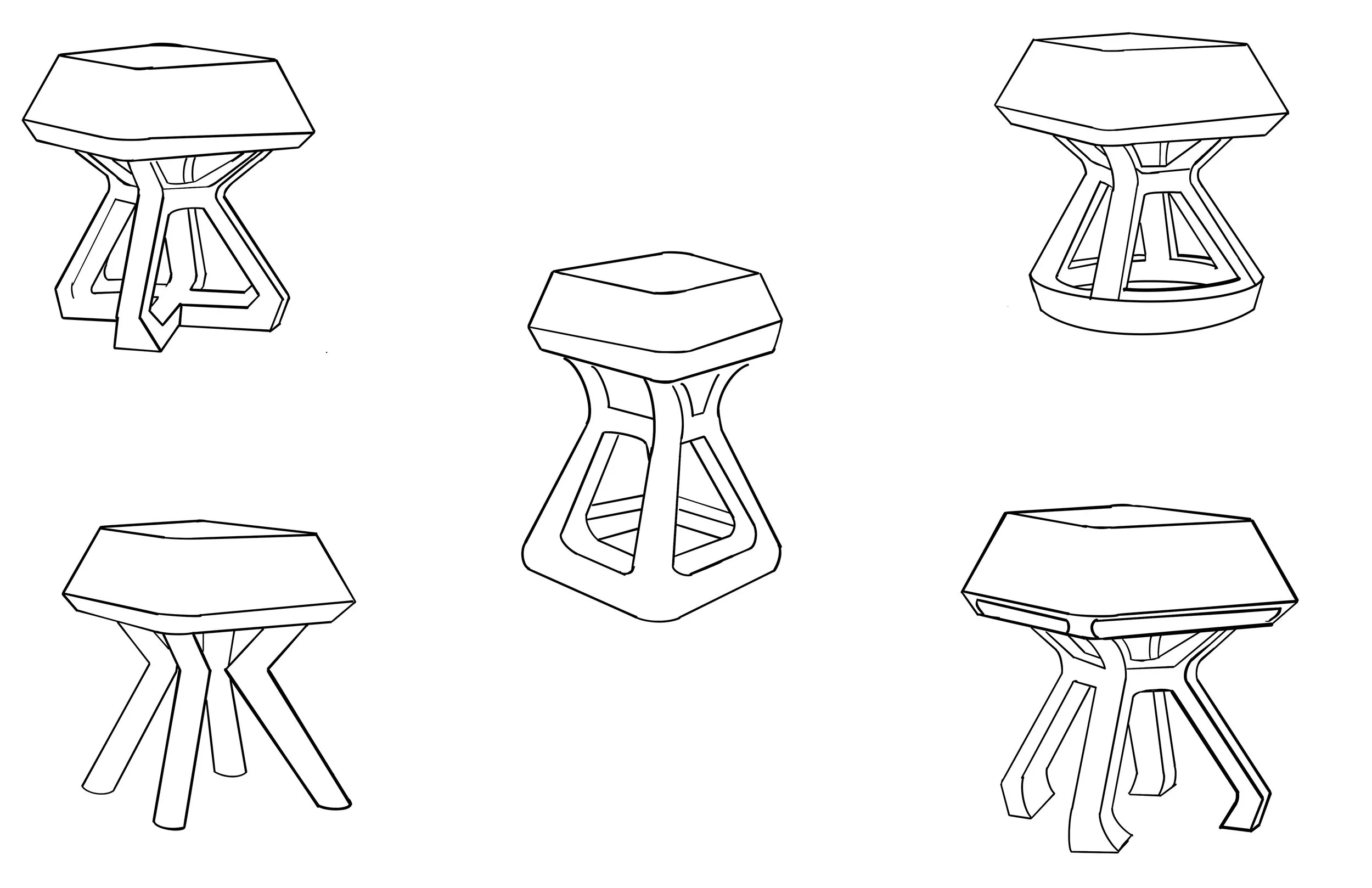
Focused Sketching
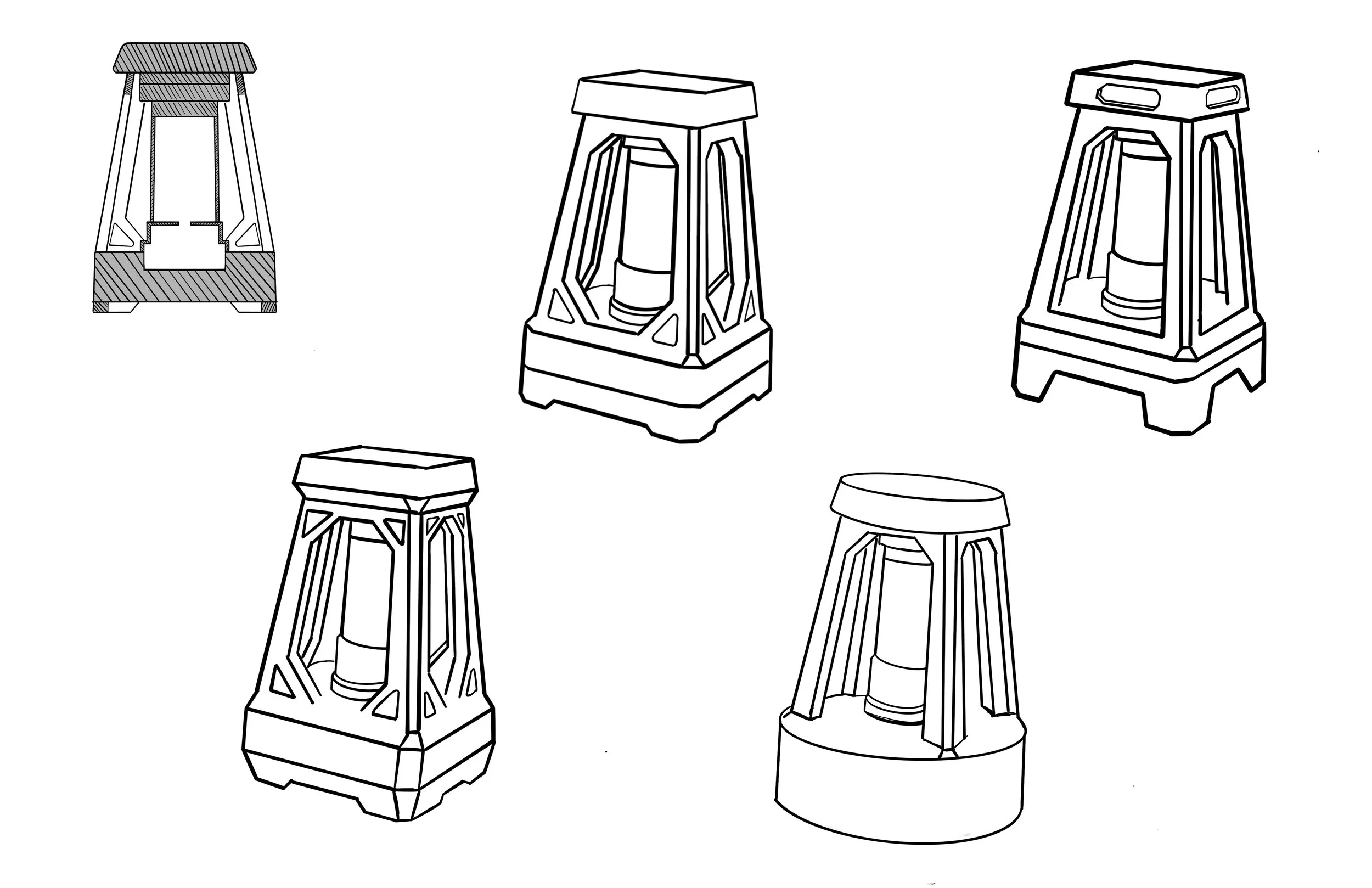
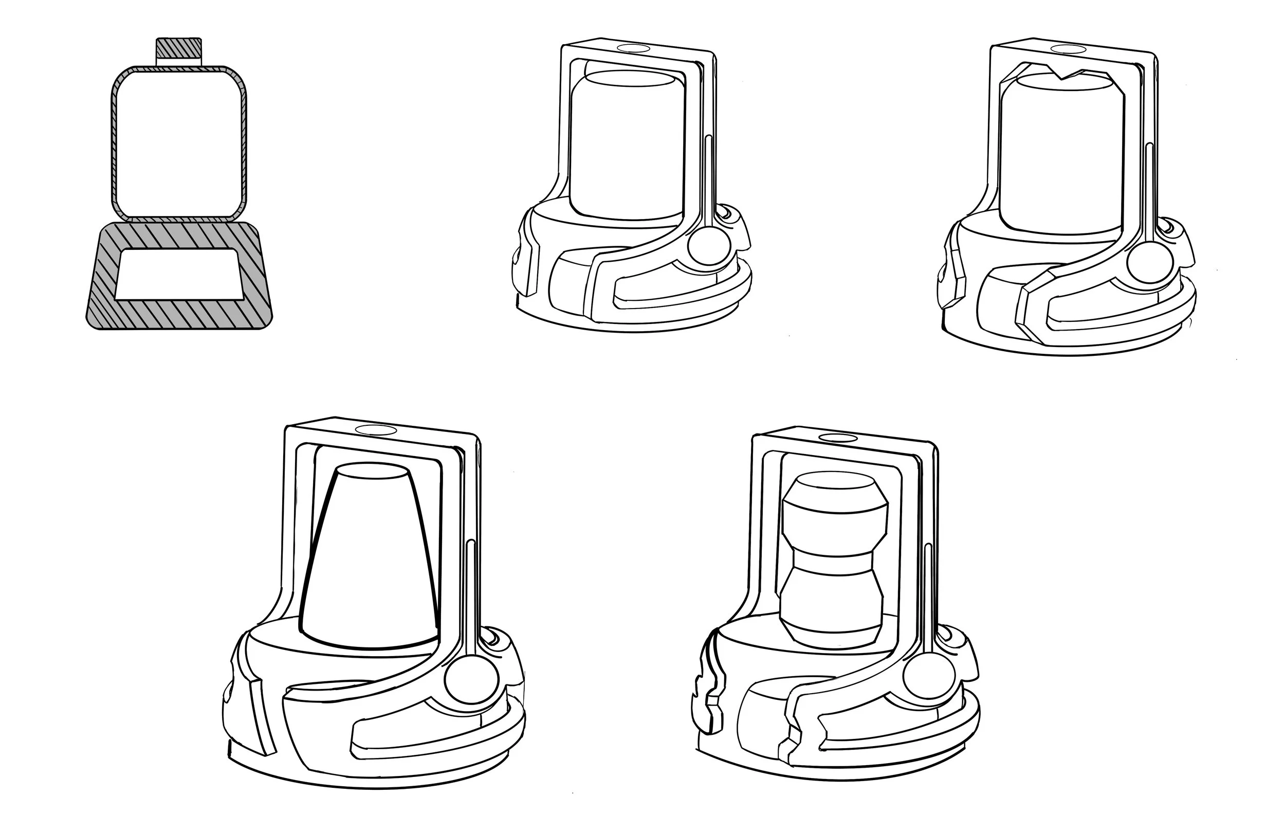
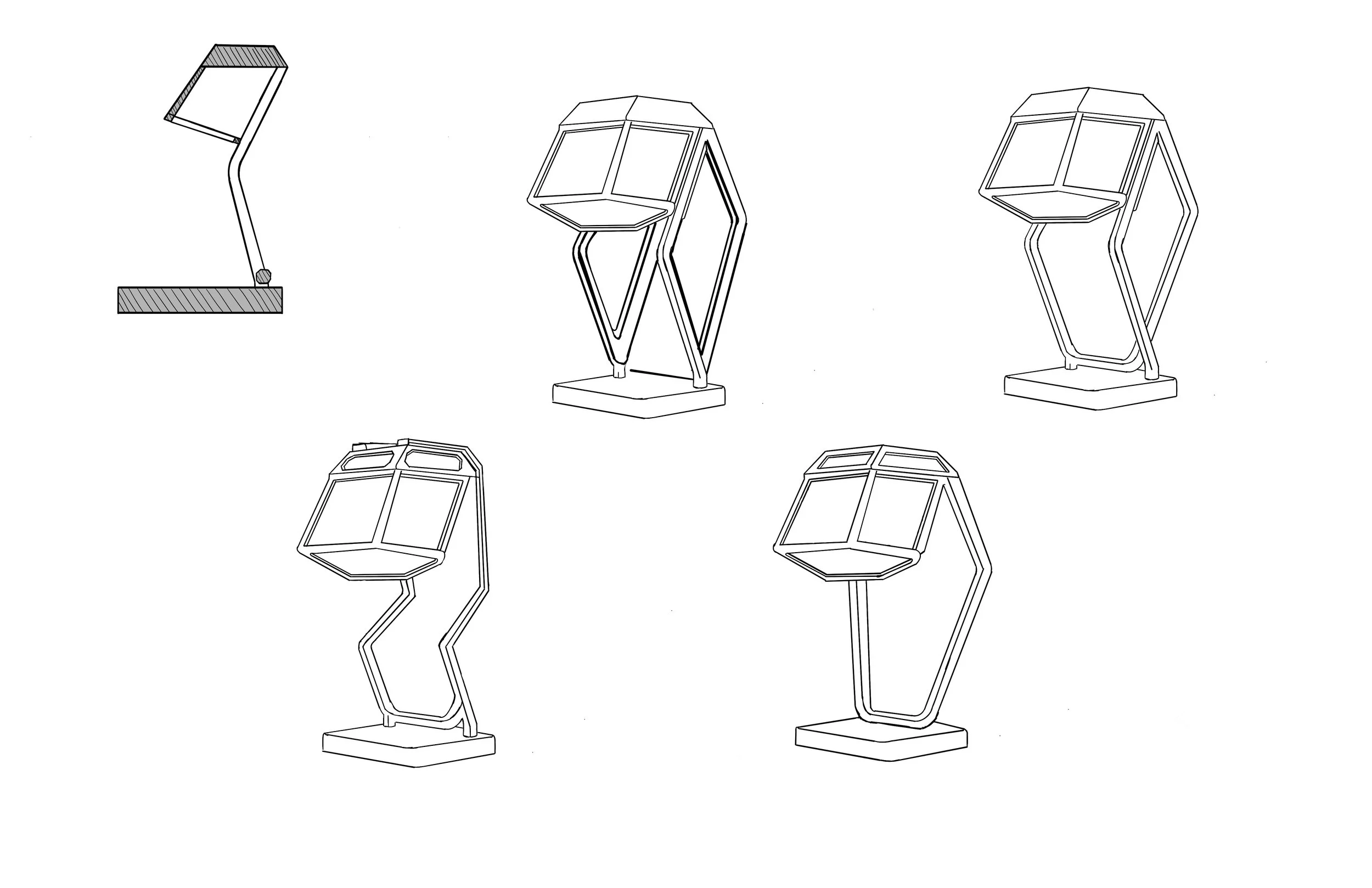
Focused Sketching & Direction Selection
Chose four key directions to refine overall form and function
Explored internal architecture to ensure space for components
Iterated silhouettes while balancing structure, layout, and usability
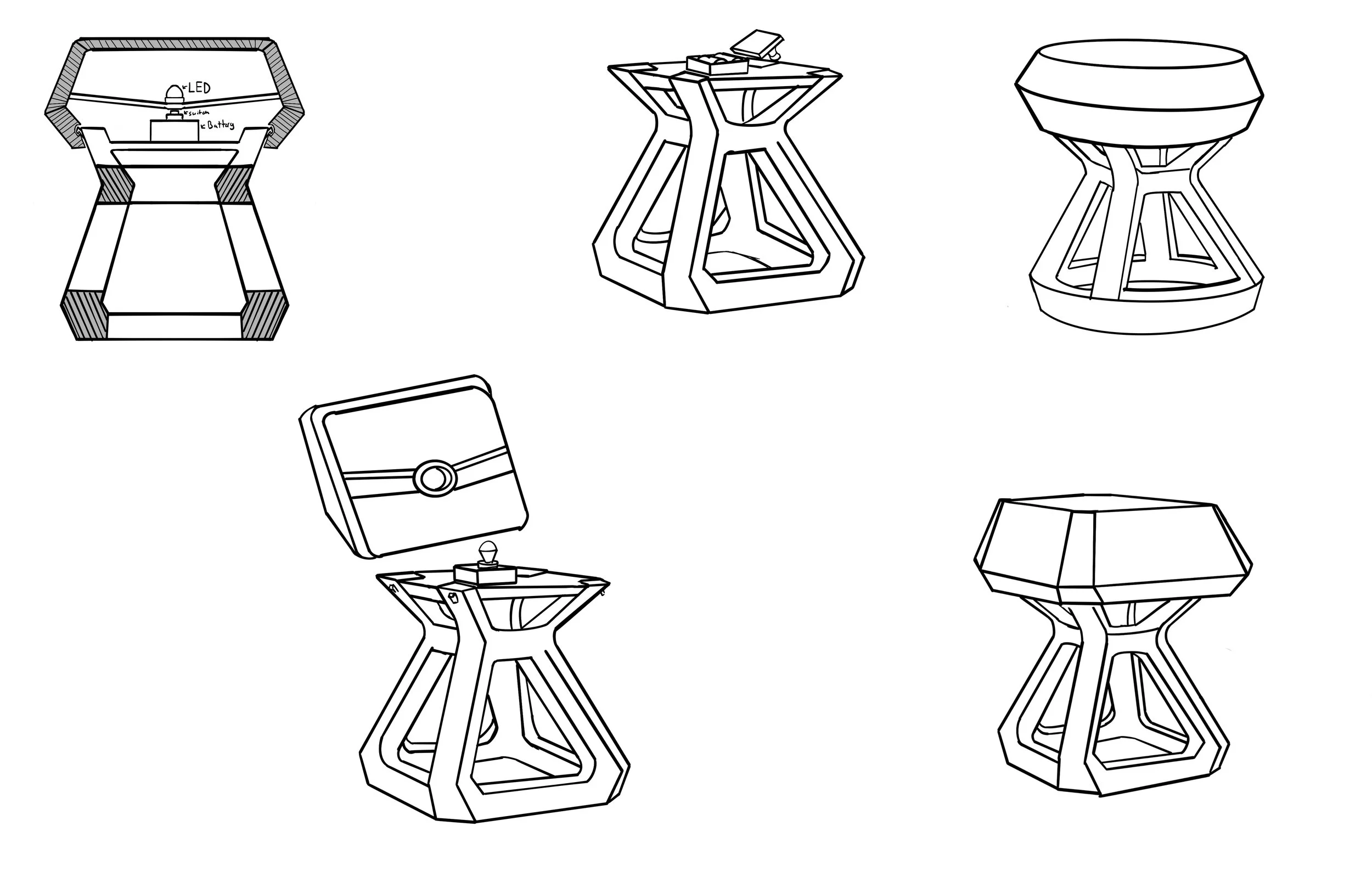
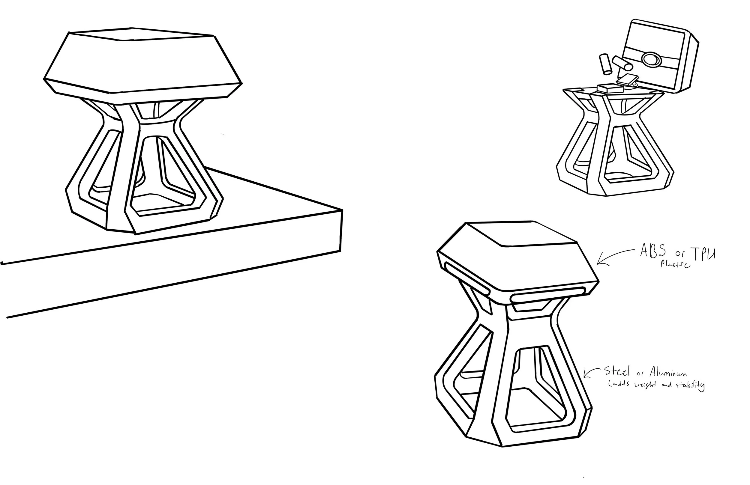
Final Direction Iterations
Finalized Form with Component + Material Layout
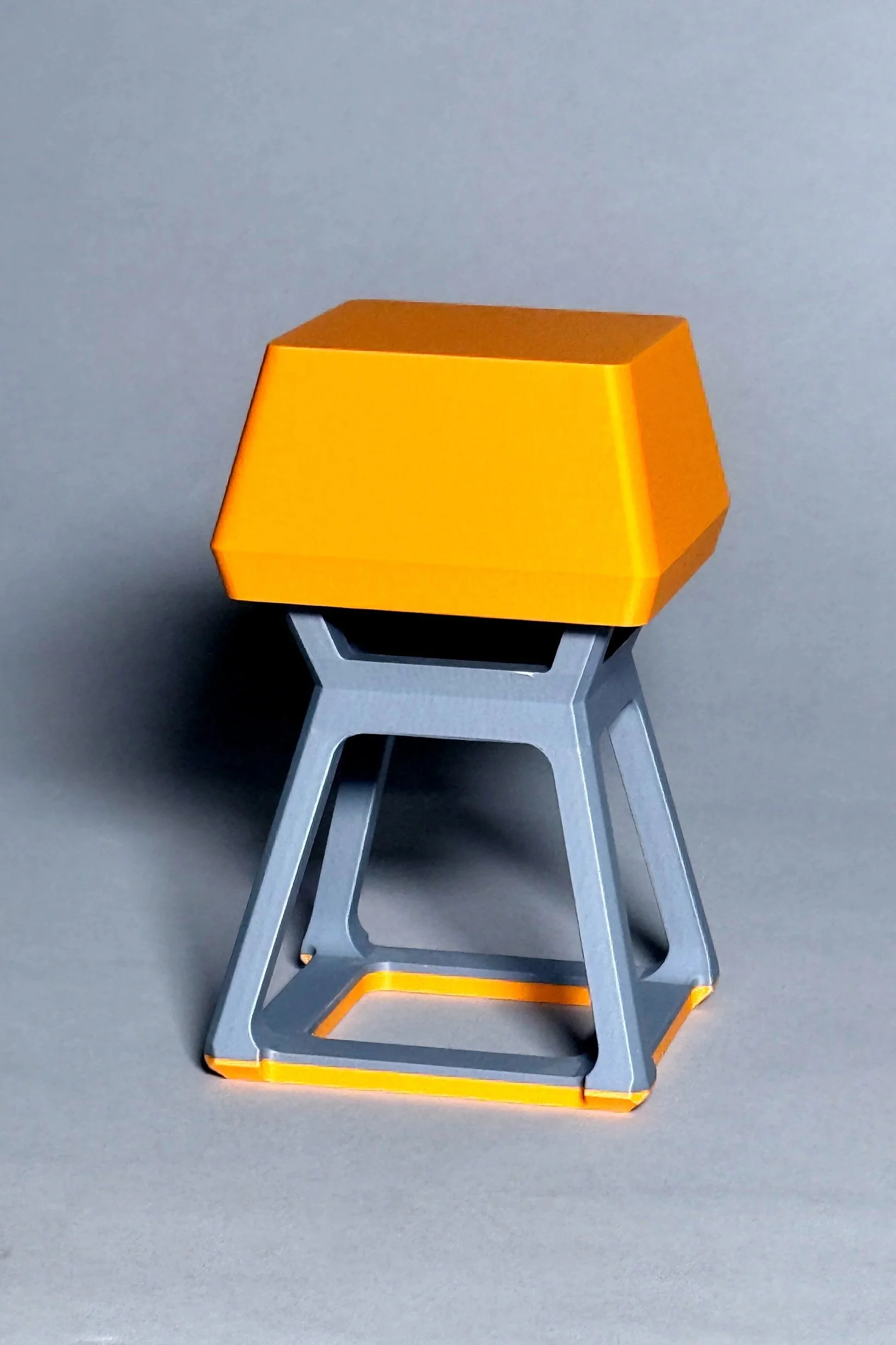
Inspired by a mechanical keycap—lamp activates by pressing the top down like a switch.
Selected final direction and refined form through targeted iterations
Laid out all internal components for clean, efficient integration
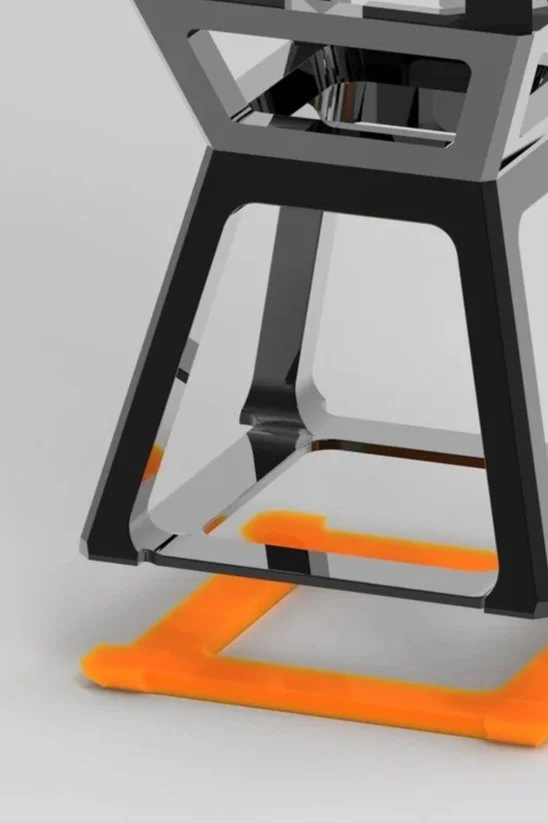
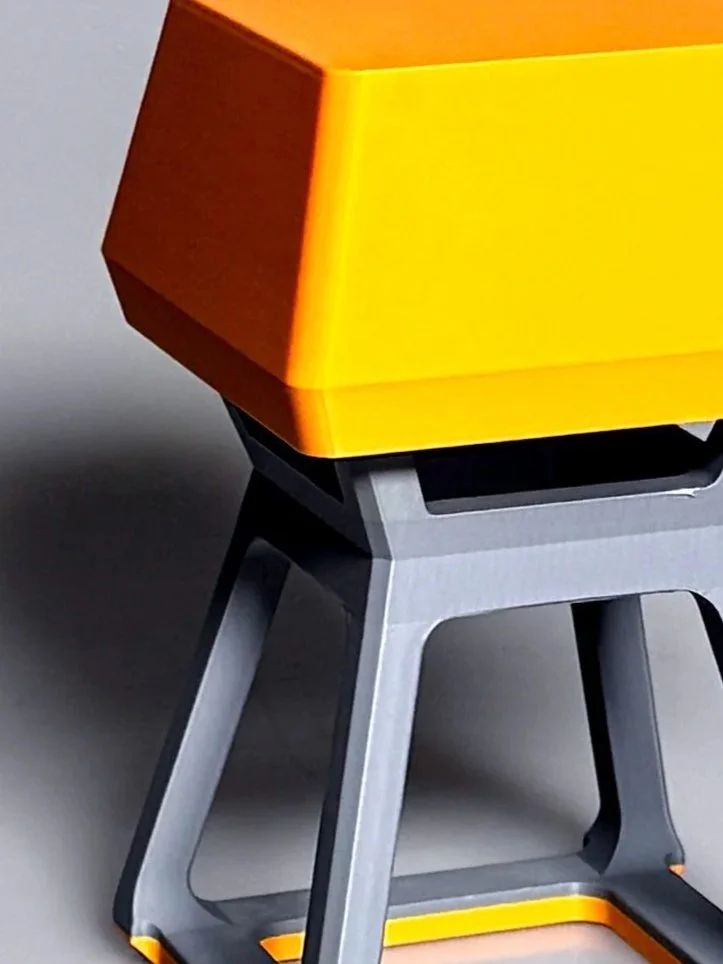
Defined materials: ABS top, steel base, silicone bottom for grip
Paper Board Models with Final Direction
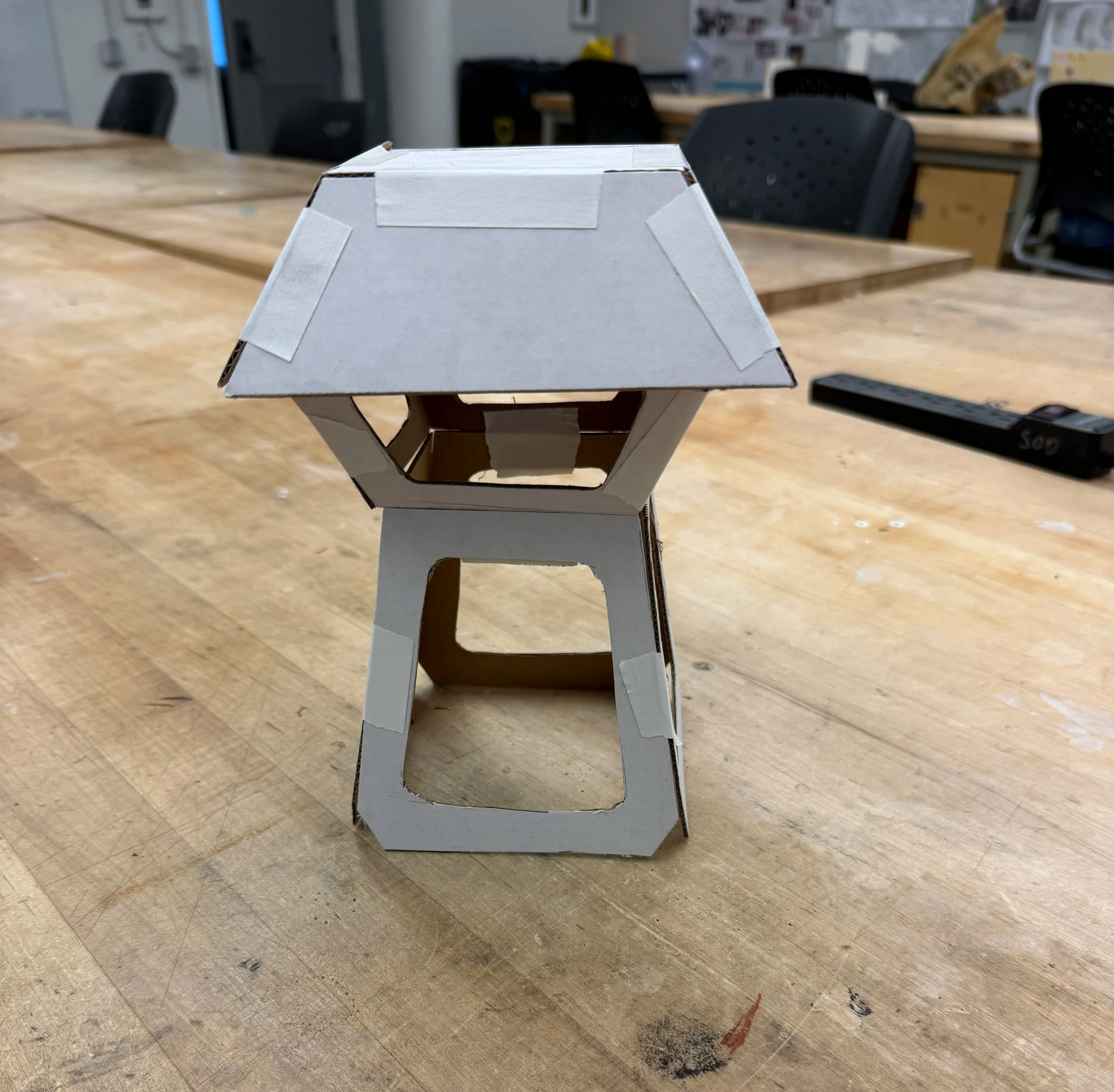
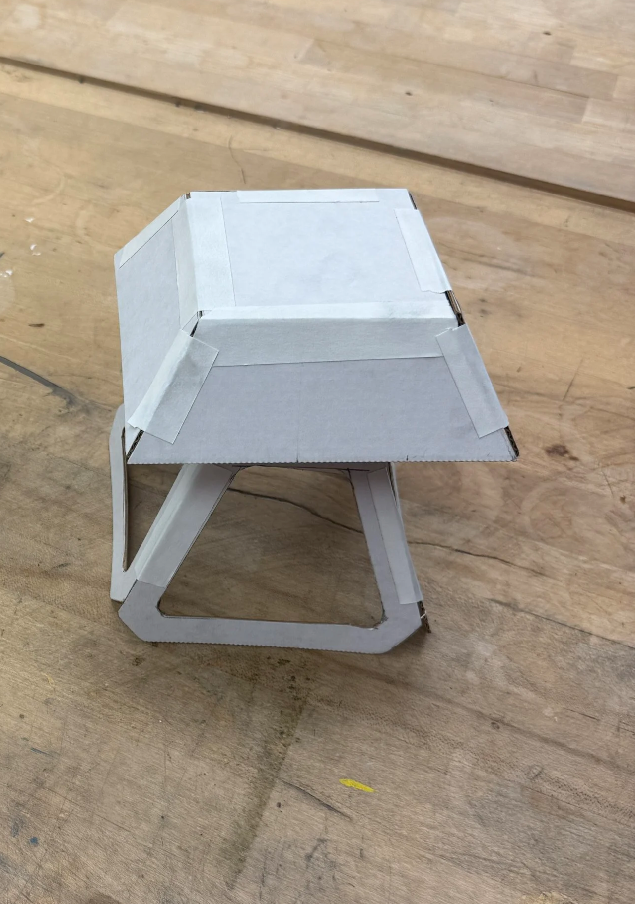
Early Paperboard Prototypes
Built paperboard models to test overall shape and volume
Helped evaluate early proportions, footprint, and general feel
Revealed need to refine height, width, and frame dimensions
Guided decisions on final scale before moving into CAD
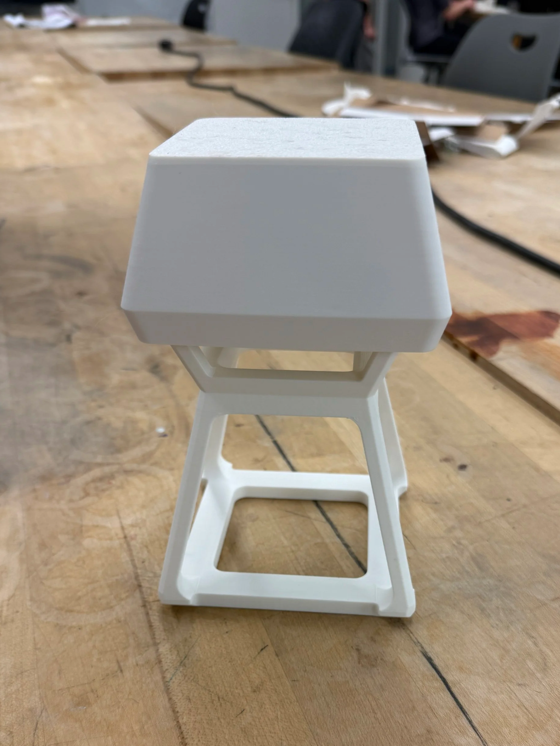
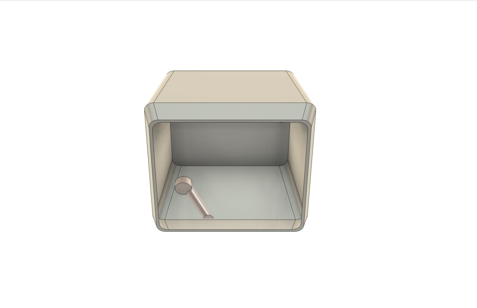
First CAD Model and 3D Print
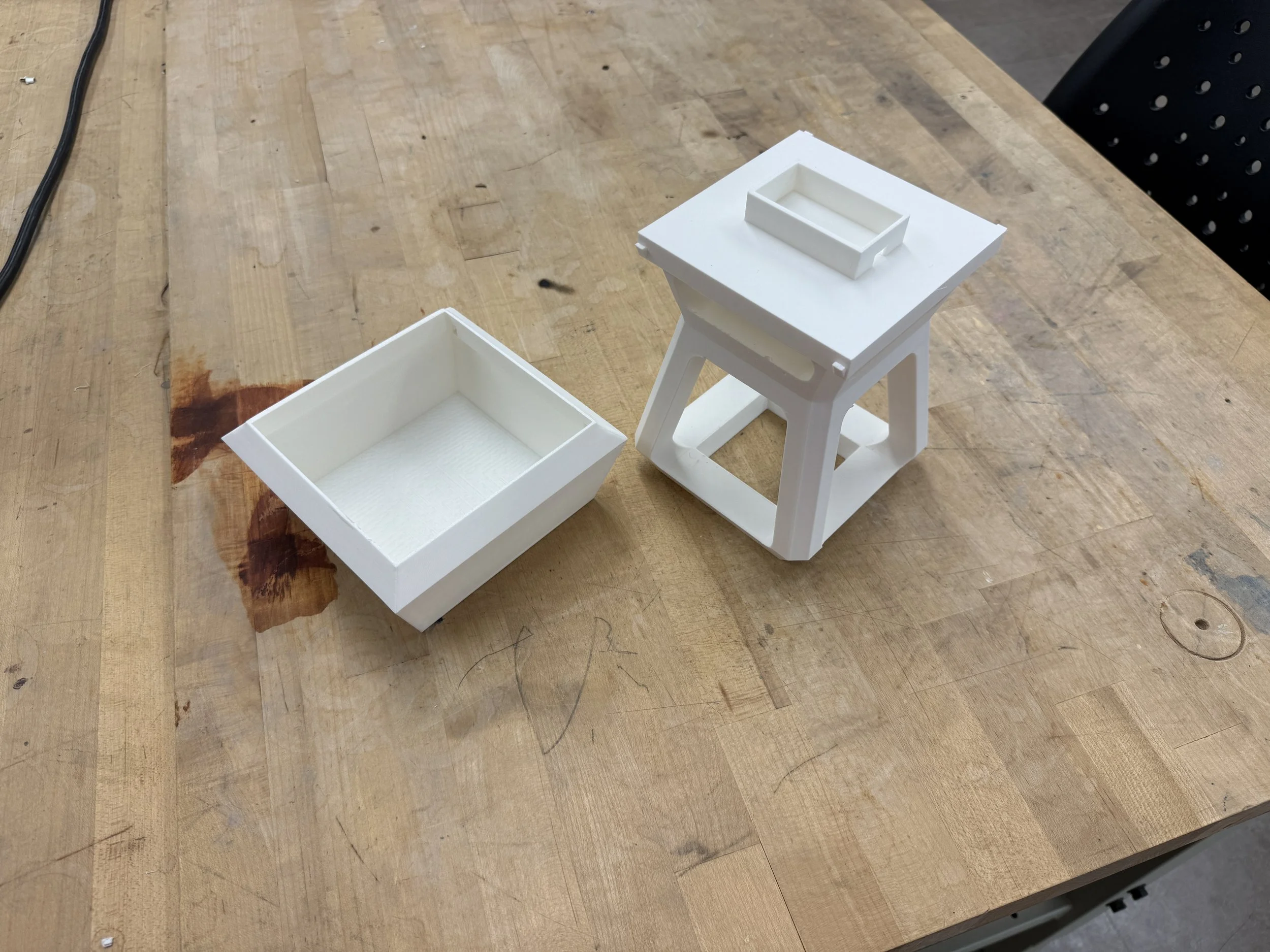
Initial Digital Model to Physical Test
Built first full CAD model and printed an early prototype
Identified areas to thin the form for cleaner proportions
Found clicking-down mechanism issues needing redesign and alignment
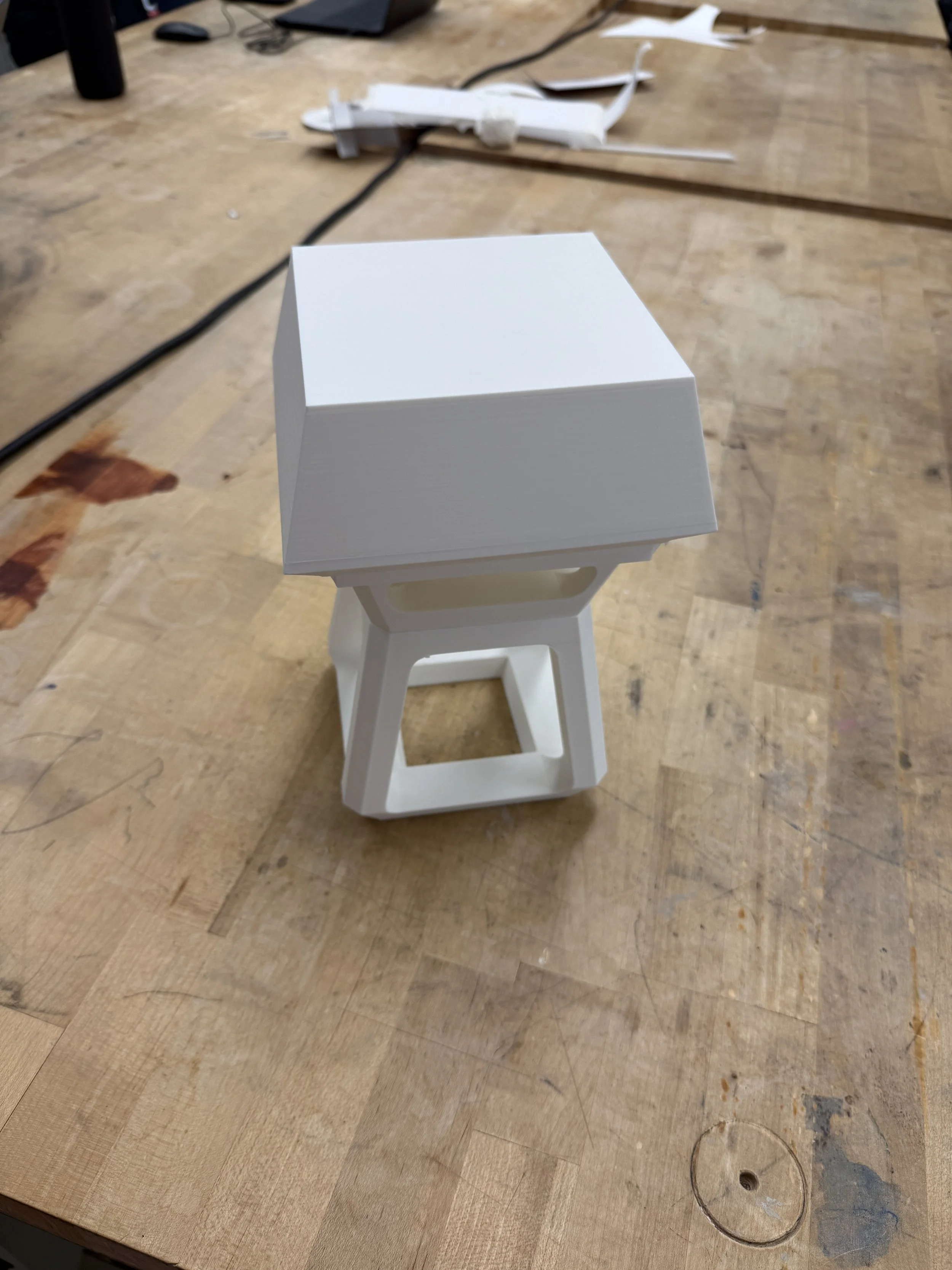
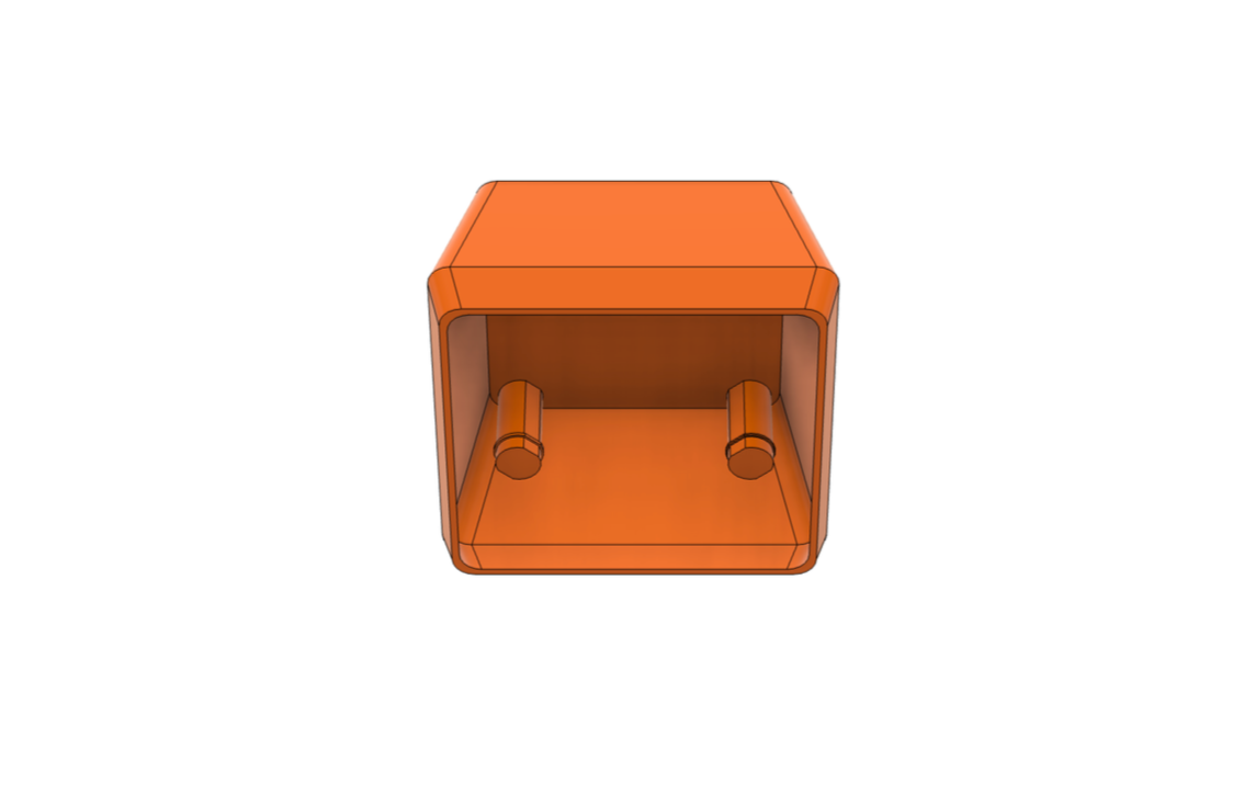
Refined CAD Model and 3D Print
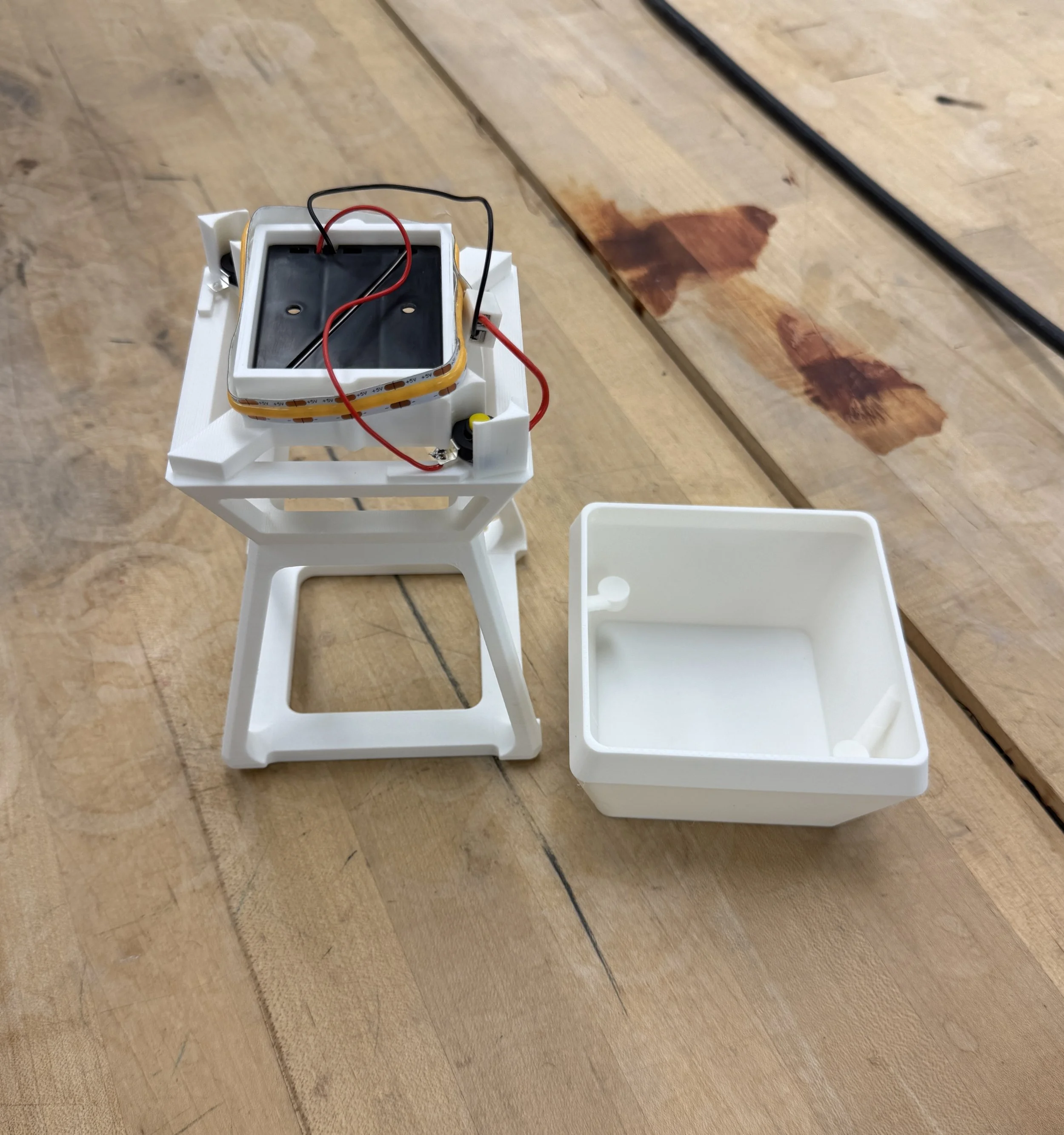
Second CAD Model & Mechanism Revision
Corrected proportions and refined surfaces for final geometry
Clicking system worked but required redesign for manufacturability
Updated component layout to support realistic production methods
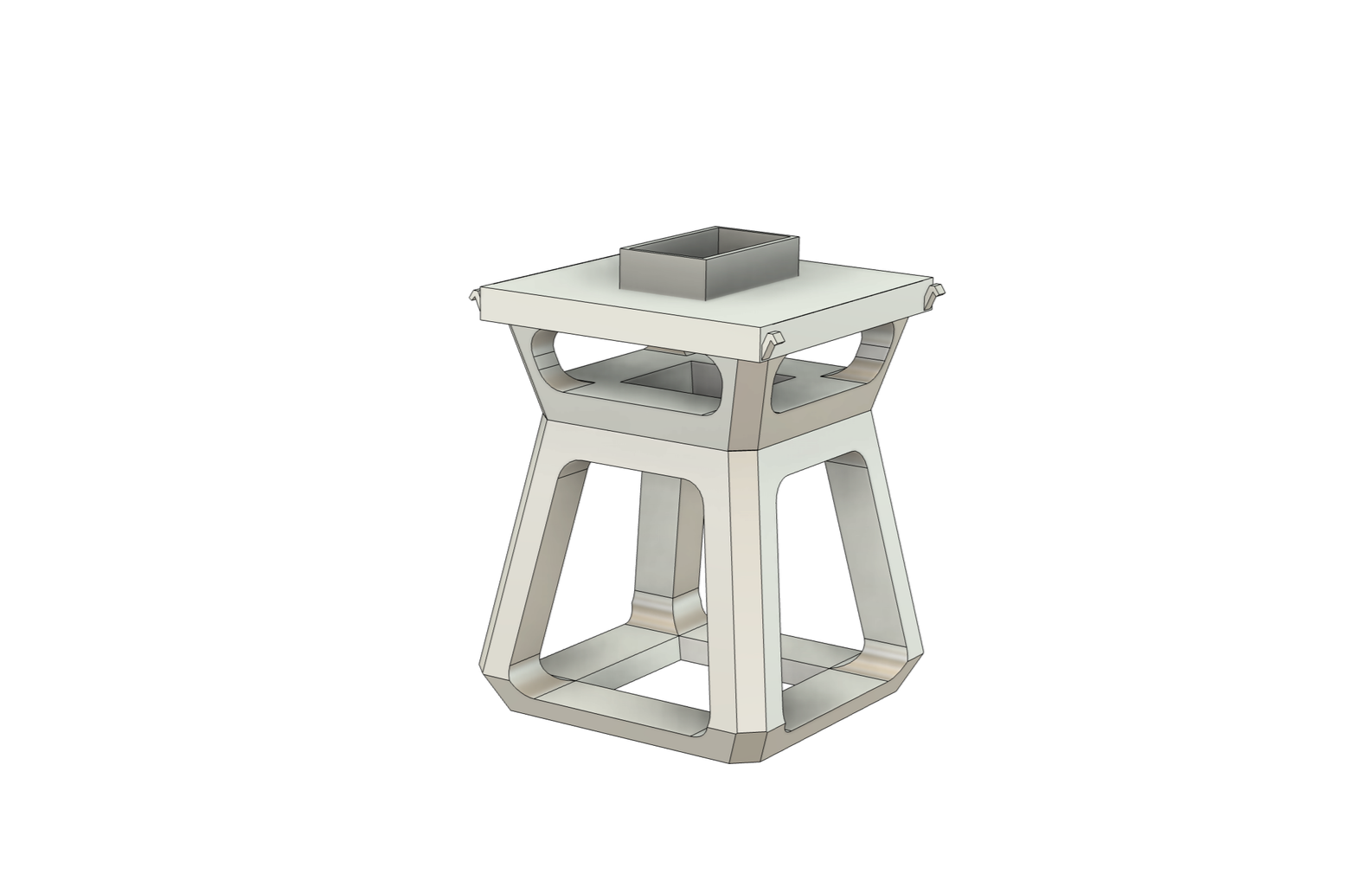
Final 3D Model
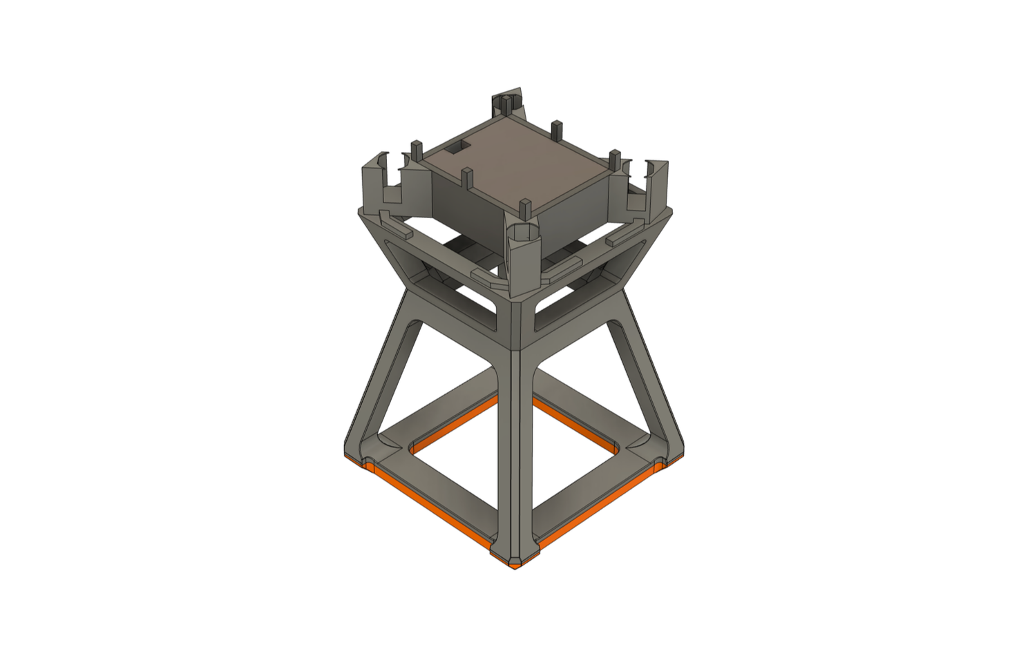
Production-Ready CAD Model
Locked in colors, materials, and final proportion adjustments
Completed production-ready click system within refined internal layout
Final CAD reflects finished design intent and mechanical function
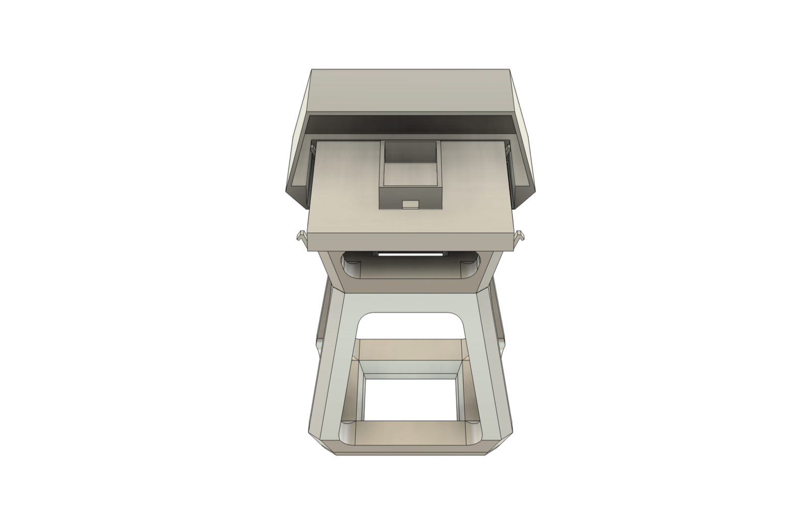
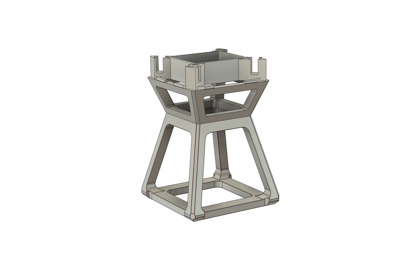
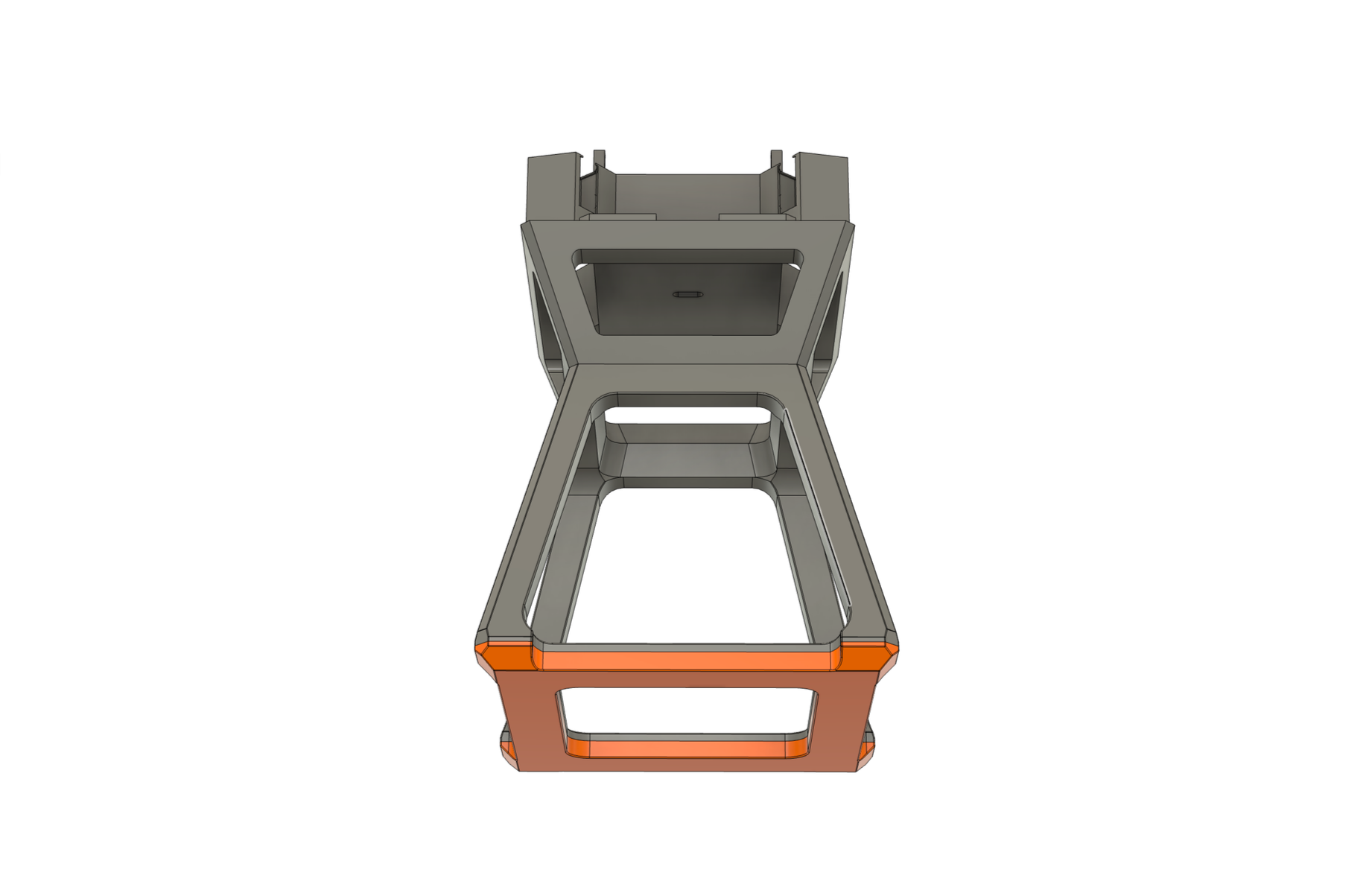
Renders and Exploded View
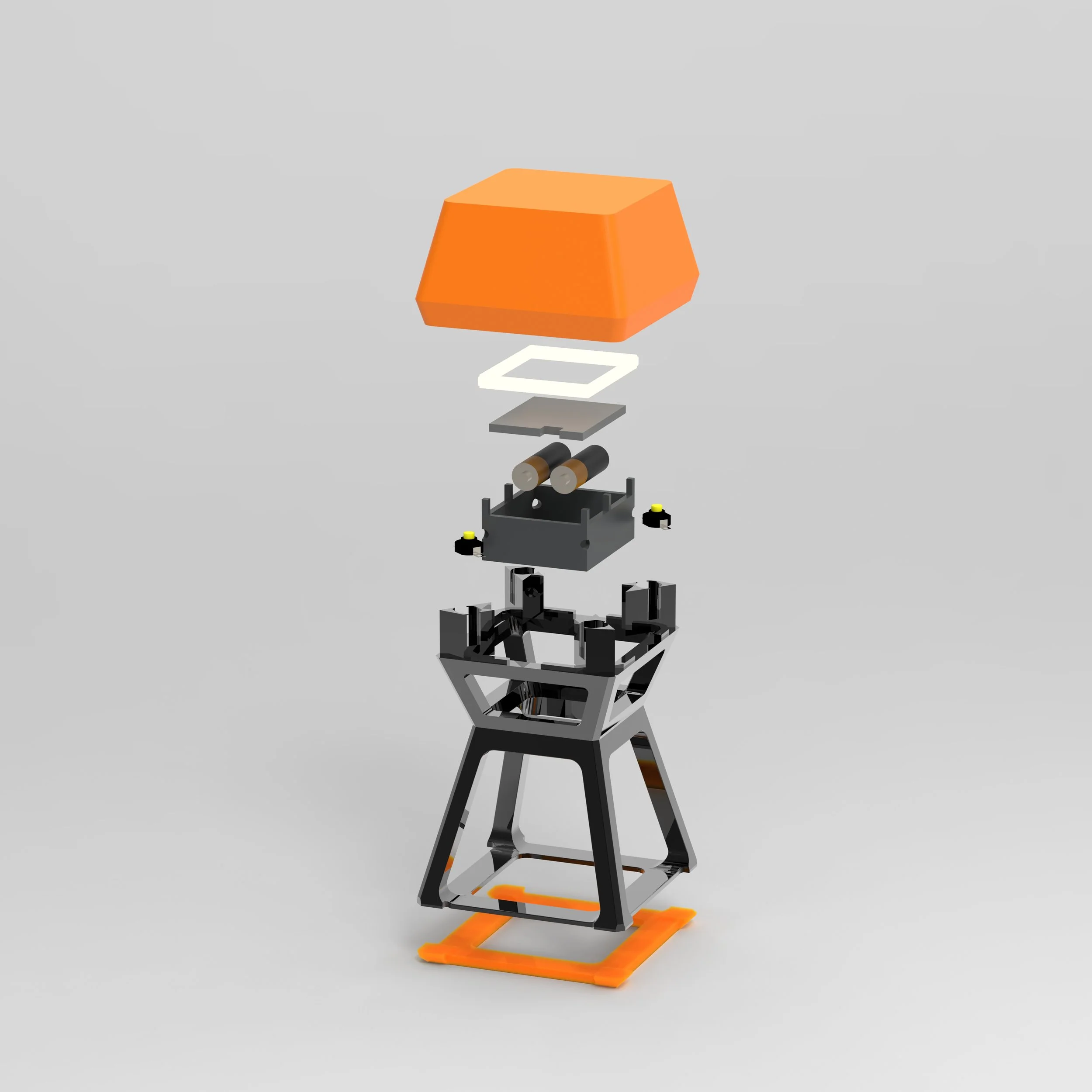
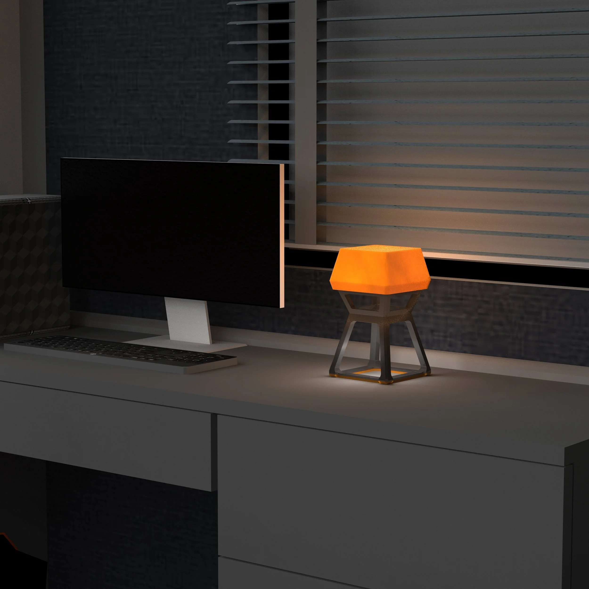
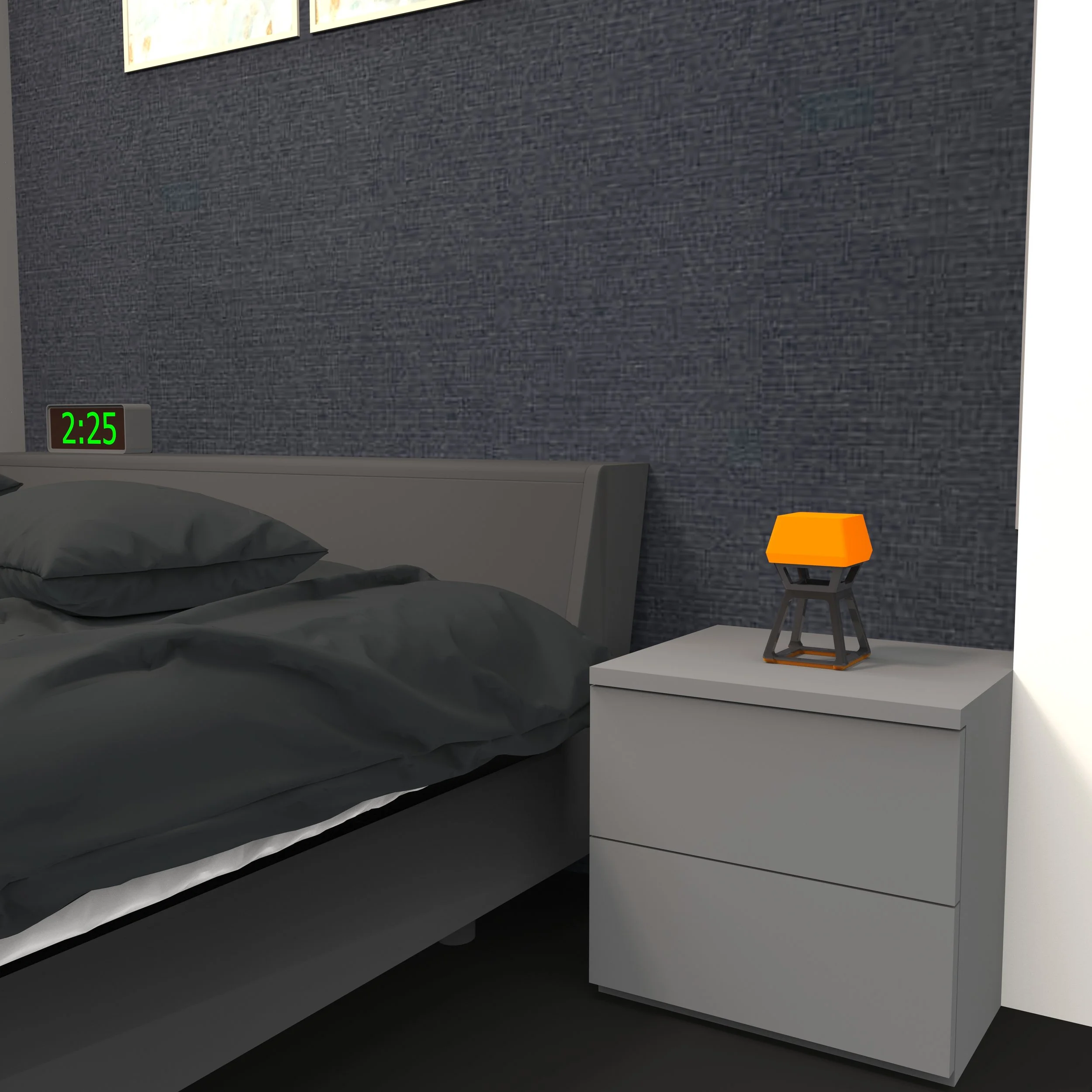
Final Renders & Exploded Architecture
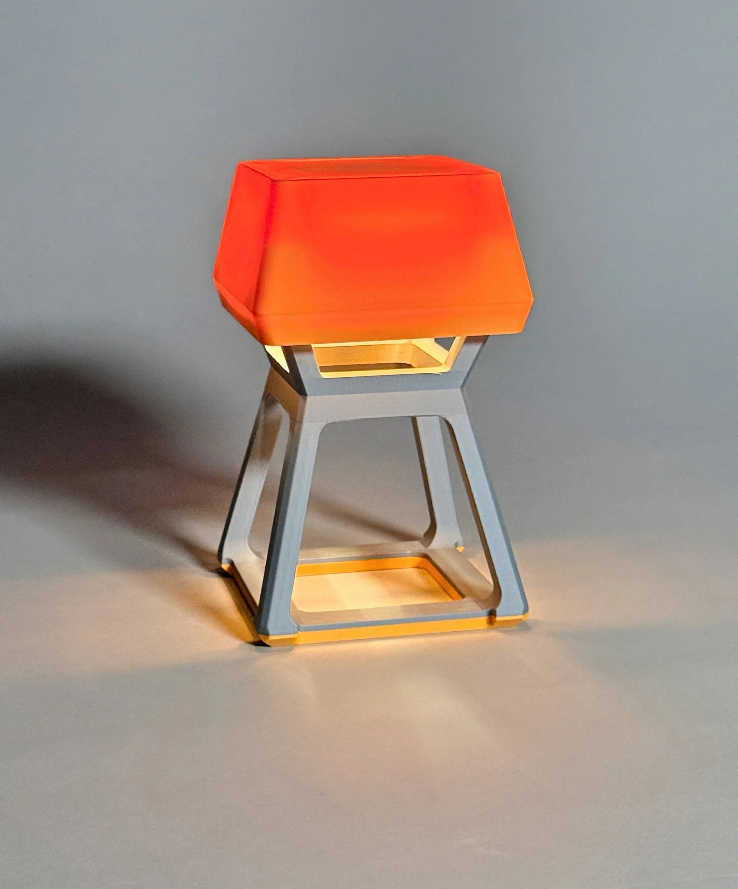
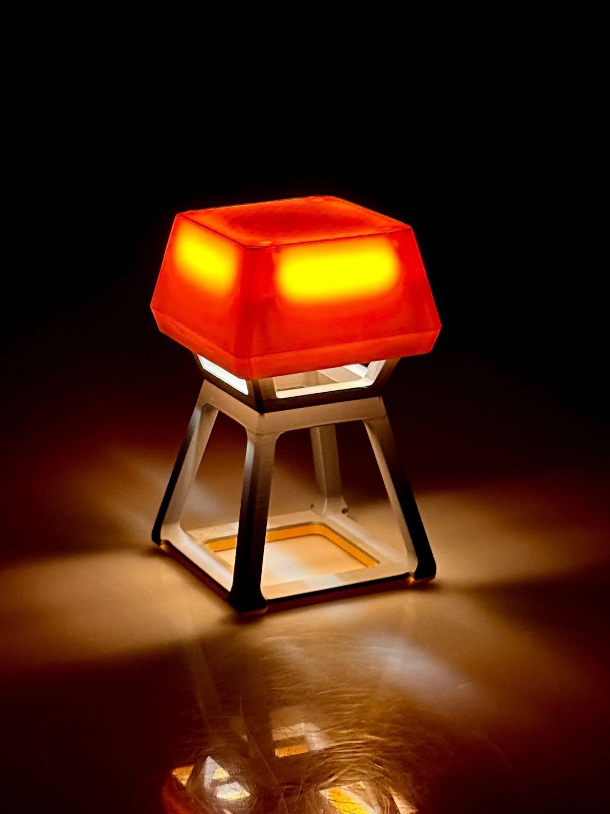
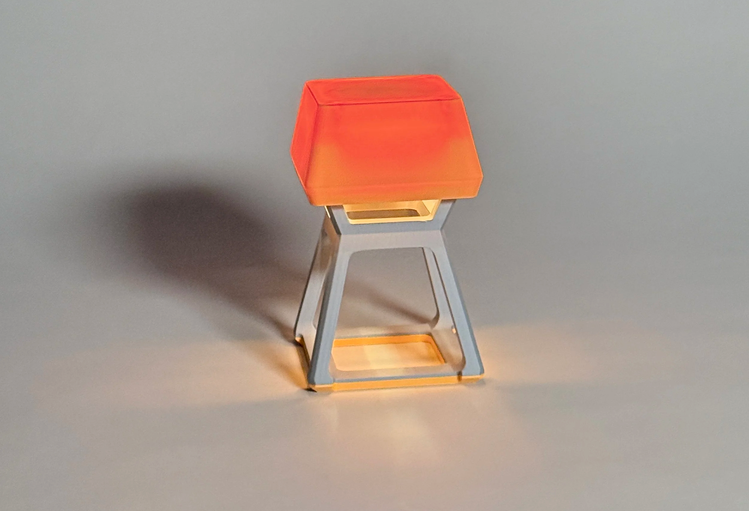
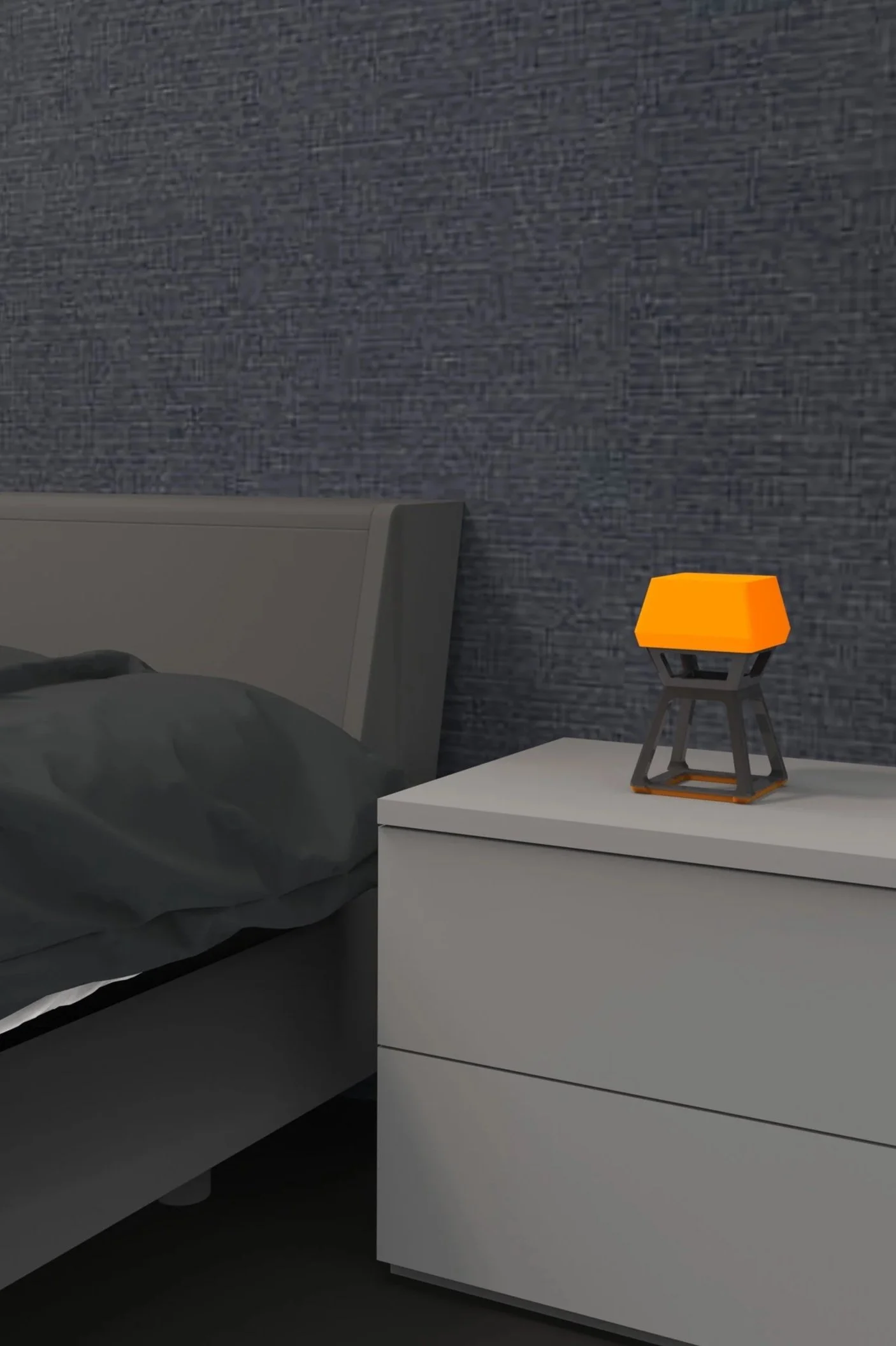
Produced context renders on desk and nightstand with lights on/off
Showcased ambient lighting effect and final visual presence
Created exploded view to reveal internal components and structure